Effect of dry ice injection pressure on surface quality
Time:2023-09-11 Category:【DSJet technology】Read:350
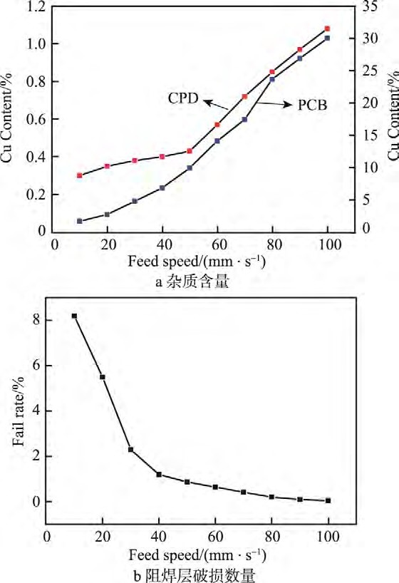
The separation method used for the sample in this experiment is laser cutting. When the laser cuts the package, the high temperature generated by the laser instantly vaporizes the epoxy resin and PCB material to form cutting grooves. The main metal element Cu in the PCB vaporizes into Cu vapor during the cutting process and splashes onto the side surface of the sample. After being subjected to high temperatures during the sputtering process, the Cu impurities are prone to delamination. Additionally, Cu impurity particles are embedded in the surface structure gaps of the encapsulant, reducing the roughness of the cutting sidewalls.
After the separation, the roughnesses (Ra) of the encapsulant and PCB area sidewalls are 7.92 μm and 8.93 μm, respectively. EDX analysis shows that the initial Cu impurity content (mass fraction) in the encapsulant and PCB areas is 1.22% and 30%, respectively.
The principle of dry ice treatment is as follows: By accelerating the flow of compressed air, dry ice particles impact the surface impurities at high speed. The impurities become brittle due to sudden cooling, and the extremely low-temperature dry ice gas enters the cracked impurity layer. As the dry ice sublimes, it rapidly expands in volume, carrying away the fragmented contaminants from the surface.
The jetting pressure significantly affects the treatment effectiveness on the material surface by influencing the explosive force of the dry ice and the instantaneous impact force on the material. The higher the jetting pressure, the greater the instantaneous impact force on the material surface per unit area, resulting in stronger removal of adhered impurities. However, if the PCB is subjected to excessive impact, microcracks caused during the cutting process will instantly propagate along the jetting direction and may even lead to detachment. In severe cases, the internal circuit structure of the PCB may be exposed, rendering the product unusable.

Figure 3a shows the influence of different jetting pressures on the removal of impurities in the encapsulant and PCB areas. It can be observed that as the jetting pressure increases, the Cu impurity content gradually decreases. However, as the pressure continues to increase, the impurity content in the encapsulant area decreases insignificantly, and the impurity content in the PCB area stabilizes only when the pressure exceeds 0.3 MPa. From the analysis of the extent of Cu impurity reduction, it can be concluded that dry ice treatment has a significant effect on removing impurities in the PCB area. At a pressure of 0.4 MPa, the Cu impurity content in the PCB area decreases from the initial 30% to 2.06%, effectively removing impurities from the PCB surface.
Figure 3b shows the effect of jetting pressure on the solder resist layer. The results indicate that when the pressure is below 0.4 MPa, the impact of dry ice on the solder resist layer is negligible. However, when the dry ice pressure exceeds 0.3 MPa, the proportion of poor solder resist layer integrity increases rapidly. Therefore, it can be concluded that a jetting pressure between 0.2-0.4 MPa achieves a balance between solder resist layer integrity and impurity removal.


